Description
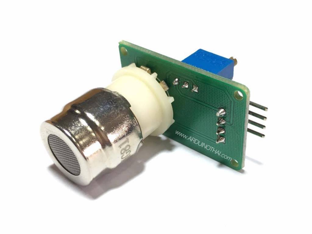
This sensor module has an MG-811 onboard as the sensor component. There is an onboard signal conditioning circuit for amplifying output signal and an onboard heating circuit for heating the sensor. The MG-811 is highly sensitive to CO2 and less sensitive to alcohol and CO. It could be used in air quality control, ferment process, in-door air monitoring application. The output voltage of the module falls as the concentration of the CO2 increases.
Features
- Analog and digital output
- Onboard signal conditioning circuit
- Onboard heating circuit
- Sensor jack eliminates soldering the sensor and allows plug-and-play
- 4-pin interlock connectors onboard
- 4-pin interlock cables included in the package
- Compact size
Getting started with the MG-811 CO2 Gas Sensor Module
The MG-811 is highly sensitive to CO2 and less sensitive to alcohol and CO. It could be used in air quality control, ferment process, in-door air monitoring application. The output voltage of the module falls as the concentration of the CO2 increases.
Hardware required
Connecting the Hardware
Connect the MG-811 CO2 Gas sensor to the arduino UNO as shown below,

Sample Code for Arduino
#define MG_PIN (0) //define which analog input channel you are going to use
#define BOOL_PIN (2)
#define DC_GAIN (8.5) //define the DC gain of amplifier
#define READ_SAMPLE_INTERVAL (50) //define how many samples you are going to take in normal operation
#define READ_SAMPLE_TIMES (5) //define the time interval(in milisecond) between each samples in
//normal operation
//These two values differ from sensor to sensor. user should derermine this value.
#define ZERO_POINT_VOLTAGE (0.220) //define the output of the sensor in volts when the concentration of CO2 is 400PPM
#define REACTION_VOLTGAE (0.020) //define the voltage drop of the sensor when move the sensor from air into 1000ppm CO2
float CO2Curve[3] = {2.602,ZERO_POINT_VOLTAGE,(REACTION_VOLTGAE/(2.602-3))};
//two points are taken from the curve.
//with these two points, a line is formed which is
//”approximately equivalent” to the original curve.
//data format:{ x, y, slope}; point1: (lg400, 0.324), point2: (lg4000, 0.280)
//slope = ( reaction voltage ) / (log400 –log1000)
void setup()
{
Serial.begin(9600); //UART setup, baudrate = 9600bps
pinMode(BOOL_PIN, INPUT); //set pin to input
digitalWrite(BOOL_PIN, HIGH); //turn on pullup resistors
Serial.print(“MG-811 Demostration\n”);
}
void loop()
{
int percentage;
float volts;
volts = MGRead(MG_PIN);
Serial.print( “SEN-00007:” );
Serial.print(volts);
Serial.print( “V ” );
percentage = MGGetPercentage(volts,CO2Curve);
Serial.print(“CO2:”);
if (percentage == -1) {
Serial.print( “<400” );
} else {
Serial.print(percentage);
}
Serial.print( “ppm” );
Serial.print(“\n”);
if (digitalRead(BOOL_PIN) ){
Serial.print( “=====BOOL is HIGH======” );
} else {
Serial.print( “=====BOOL is LOW======” );
}
Serial.print(“\n”);
delay(200);
}
float MGRead(int mg_pin)
{
int i;
float v=0;
for (i=0;i<READ_SAMPLE_TIMES;i++) {
v += analogRead(mg_pin);
delay(READ_SAMPLE_INTERVAL);
}
v = (v/READ_SAMPLE_TIMES) *5/1024 ;
return v;
}
int MGGetPercentage(float volts, float *pcurve)
{
if ((volts/DC_GAIN )>=ZERO_POINT_VOLTAGE) {
return -1;
} else {
return pow(10, ((volts/DC_GAIN)-pcurve[1])/pcurve[2]+pcurve[0]);
}
}
Testing the circuit
Open the serial monitor and you will get the concentration of the CO2 around you .


