Description
Ever wondered how your smartphone knows up from down! It’s one of the coolest features of today’s smartphones. They all got a tiny device called Accelerometer built into the circuitry which can sense when you tilt it from side to side. That’s how your smartphone automatically figures out when to switch the screen layout from portrait to landscape.
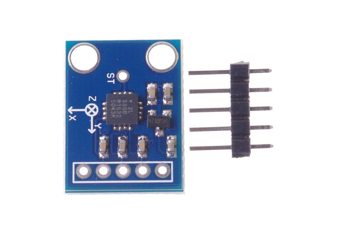
Sensor Chip: ADXL335.
Operating voltage: 3V-5V.
Interface: Analogue output.
Operating temperature: -40 +85.
X, Y, Z output
Three-axis accelerometer module magnetic field.
Getting started with the ADXL335 Module 3-axis Analog Output Accelerometer angular transducer
This tutorial shows you how to read from the ADXL335 accelerometer and receive the values in the serial monitor of the Arduino Software (IDE) or another application that receives data over the serial port.
Step1: Hardware required
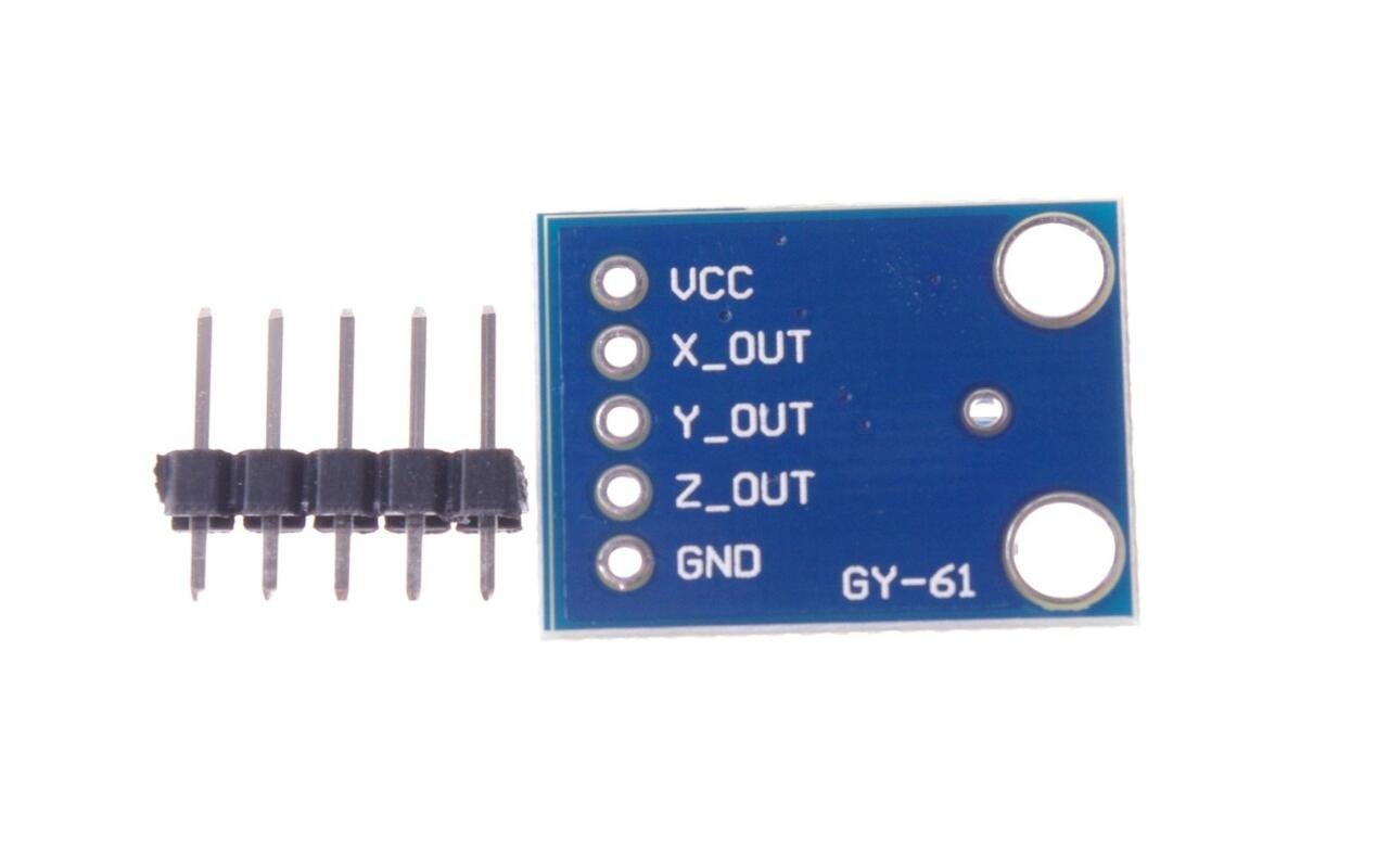
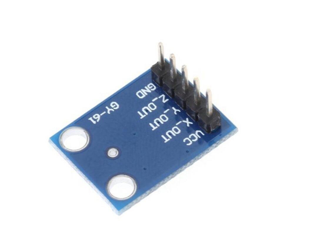
ADXL335 Accelerometer Pinout
Before diving into hookup and example code, let’s first take a look at its Pinout.

Step2: Connecting the Hardware
Connections are pretty easy. Start by placing the accelerometer on to your breadboard. Connect VCC pin to the 5V pin on the Arduino and connect GND pin to the Ground pin on the Arduino. Also connect X, Y and Z output to the analog pins A0, A1 and A2 on Arduino.
For accurate results, we need to change the analog reference(AREF) voltage of the Arduino. This can be done by connecting the 3.3V pin on Arduino to the AREF pin.
When you’re done you should have something that looks similar to the illustration shown below.

Step3: Upload the sample sketch
const int xInput = A0;
const int yInput = A1;
const int zInput = A2;
// initialize minimum and maximum Raw Ranges for each axis
int RawMin = 0;
int RawMax = 1023;
// Take multiple samples to reduce noise
const int sampleSize = 10;
void setup()
{
analogReference(EXTERNAL);
Serial.begin(9600);
}
void loop()
{
//Read raw values
int xRaw = ReadAxis(xInput);
int yRaw = ReadAxis(yInput);
int zRaw = ReadAxis(zInput);
// Convert raw values to ‘milli-Gs”
long xScaled = map(xRaw, RawMin, RawMax, -3000, 3000);
long yScaled = map(yRaw, RawMin, RawMax, -3000, 3000);
long zScaled = map(zRaw, RawMin, RawMax, -3000, 3000);
// re-scale to fractional Gs
float xAccel = xScaled / 1000.0;
float yAccel = yScaled / 1000.0;
float zAccel = zScaled / 1000.0;
Serial.print(“X, Y, Z :: “);
Serial.print(xRaw);
Serial.print(“, “);
Serial.print(yRaw);
Serial.print(“, “);
Serial.print(zRaw);
Serial.print(” :: “);
Serial.print(xAccel,0);
Serial.print(“G, “);
Serial.print(yAccel,0);
Serial.print(“G, “);
Serial.print(zAccel,0);
Serial.println(“G”);
delay(200);
}
// Take samples and return the average
int ReadAxis(int axisPin)
{
long reading = 0;
analogRead(axisPin);
delay(1);
for (int i = 0; i < sampleSize; i++)
{
reading += analogRead(axisPin);
}
return reading/sampleSize;
}
NOTE: If you get stray ‘223’ in program the problem is with your “and” characters .Replace them with ordinary quotes “. And you should be fine.
Step4: Testing the circuit
Following image shows the accelerometer output on serial monitor at different positions.


