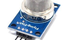
Description
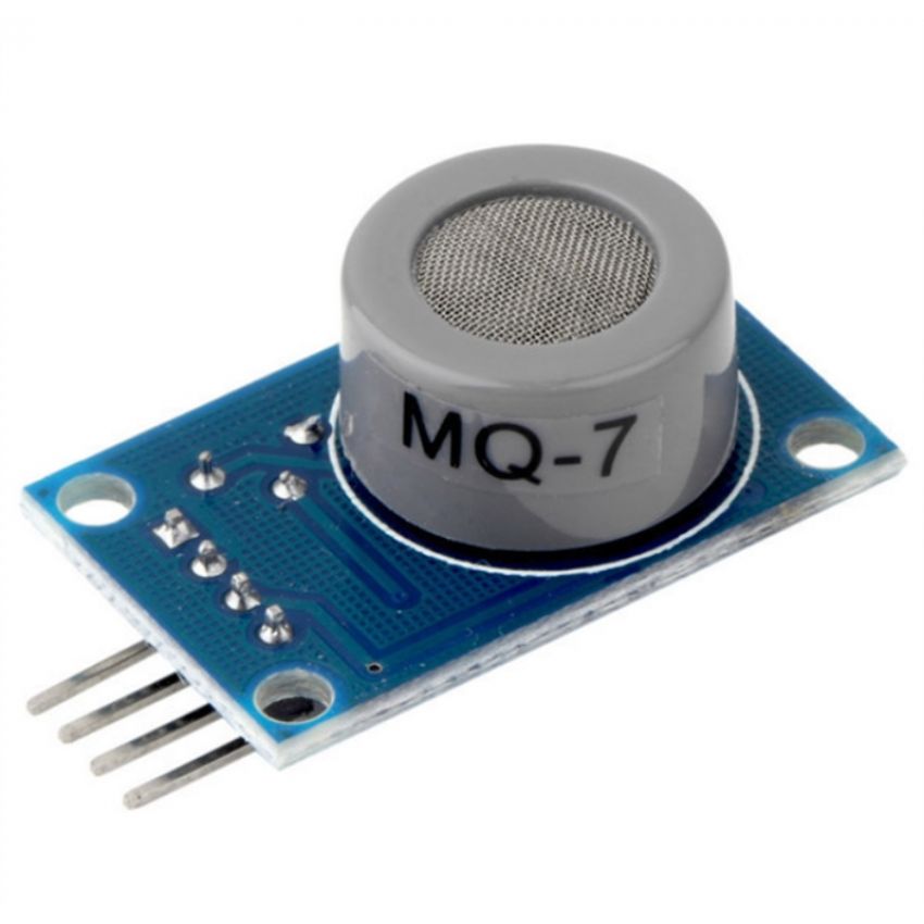
This is a simple-to-use Carbon Monoxide (CO) sensor, suitable for sensing CO concentrations in the air. The MQ-7 can detect CO-gas concentrations anywhere from 20 to 2000ppm.
This sensor has a high sensitivity and fast response time. Mainly used for CO collection detection in family, factory, underground operation.
Specifications:
Heater voltage: 50.2V(ACDC)
Working voltage: 140mA
Loop voltage: 0V(Maximum DC 15V)
Loading resistance: 10K (adjustable)
Detecting concentration range: 10-1000ppm
Voltage in cleaning air: 1.5V
Sensitivity: 3%
Response time: 1S (preheating 3-5 minutes)
Reply time: 30S
Component power consumption: 0.7W
Working temperature: -10~50 degree (nominal temperature: 20 degree)
Working humidity: 95%RH (nominal humidity: 65%RH)
Getting started with the Carbon Monoxide Sensor – (MQ-7)
In this project, we will go over how to build a carbon monoxide sensor circuit with an arduino. The carbon monoxide sensor we will use is the MQ-7 sensor. This is a sensor that is sensitive to effects of CO.
Carbon monoxide (CO) is a very dangerous gas which is odorless, colorless, and tasteless, so it cannot be smelt, seen, or tasted. A person really would have no idea that they are breathing in CO besides the fact that they would start to feel horrible. The most common symptoms of CO poisoning is headache, nausea, vomiting, dizziness, fatigue, and a feeling of weakness. Neurological signs include confusion, disorientation, visual disturbance, syncope, and seizures.
Hardware required
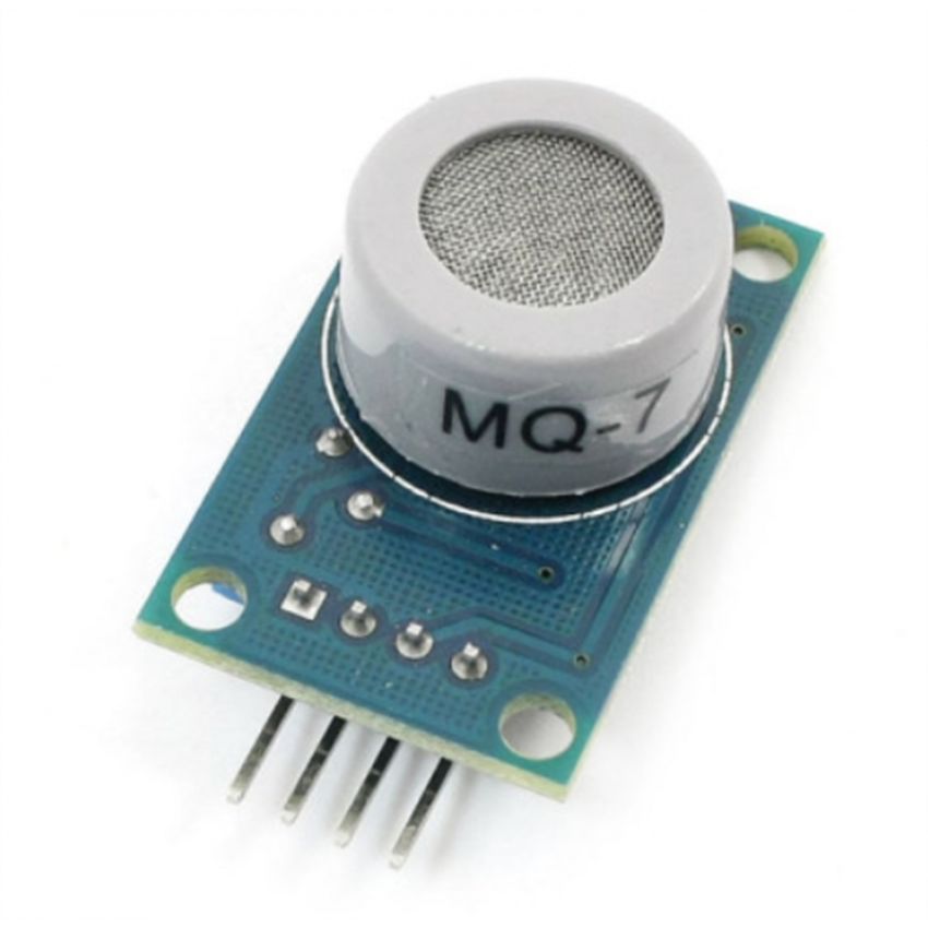
there are 4 leads which need to be connected.

There 4 leads are +5V, AOUT, DOUT, and GND.
The +5V and GND leads establishes power for the alcohol sensor.
The other 2 leads are AOUT (analog output) and DOUT (digital output). How the sensor works is the terminal AOUT gives an analog voltage output in proportion to the amount of carbon monoxide the sensor detects. The more CO it detects, the greater the analog voltage it will output. Conversely, the less CO it detects, the less analog voltage it will output. If the analog voltage reaches a certain threshold, it will send the digital pin DOUT high. Once this DOUT pin goes high, the arduino will detect this and will trigger the LED to turn on, signaling that the CO threshold has been reached and is now over the limit. How you can change this threshold level is by adjusting the potentiometer to either raise or lower the level.
Connecting the Hardware
The carbon monoxide sensor circuit we will build with an MQ-7 sensor integrated with an arduino is shown below.

The connections are pretty basic.
To connect the sensor, there are 4 leads. 2 of them are for power. The +5V terminal of the sensor connects into the 5V terminal of the arduino board. The GND terminal of the sensor connects into the GND terminal of the arduino. This establishes power for the sensor. The other 2 connections are the analog and digital output of the sensor. These connect to analog pin A0 and digital pin D8, respectively.
Code
The code which we need to upload to the arduino so that it can measure carbon monoxide levels is shown below.
/* MQ-7 Carbon Monoxide Sensor Circuit with Arduino */
const int AOUTpin = 0; //the AOUT pin of the CO sensor goes into analog pin A0 of the arduino
const int DOUTpin = 8; //the DOUT pin of the CO sensor goes into digital pin D8 of the arduino
const int ledPin = 13; //the anode of the LED connects to digital pin D13 of the arduino
int limit;
int value;
void setup() {
Serial.begin(115200);//sets the baud rate
pinMode(DOUTpin, INPUT);//sets the pin as an input to the arduino
pinMode(ledPin, OUTPUT);//sets the pin as an output of the arduino
}
void loop()
{
value = analogRead(AOUTpin); //reads the analaog value from the CO sensor’s AOUT pin
limit = digitalRead(DOUTpin); //reads the digital value from the CO sensor’s DOUT pin
Serial.print(“CO value: “);
Serial.println(value);//prints the CO value
Serial.print(“Limit: “);
Serial.print(limit);//prints the limit reached as either LOW or HIGH (above or underneath)
delay(100);
if (limit == HIGH) {
digitalWrite(ledPin, HIGH);//if limit has been reached, LED turns on as status indicator
}
else {
digitalWrite(ledPin, LOW);//if threshold not reached, LED remains off
}
}
NOTE: IF you get stray ‘223’ in program The problem is with your “and ” characters. Replace them with ordinary quotes ” ” and you should be fine.
The first block of code defines all the pin connections of the sensor and the LED. Since the AOUTpin connects to analog pin A0, it is initialized to 0. Since the DOUTpin connects to digital pin D8, it is initialized to 8. Since the LED connects to digital pin D13, it is initialized to 13. 2 variables, limit and value, are also declared. These will be used to store the value of the analog pin AOUT and digital pin DOUT.
The next block of code sets the baud rate and declares the DOUTpin as input and the ledPin as output. This is because the sensor is an input to the arduino for the arduino to read and process the sensor value. And the LED is an output will serves an indicator if the sensor has detected alcohol.
The next block of code reads the sensor pin AOUT and stores the value in the integer value. It also reads the sensor pin DOUT and stores the value in the integer limit. We then print the alcohol value, which will be a numeric value ranging from either 0 (no alcohol detected) to 1023 (maximum level of carbon monoxide that can be read). We will aslo print the limit which will either be HIGH or LOW. If the CO detected is under the threshold level, the value of limit returned will be low. If the CO detected is above the threshold, the value of limit returned will be HIGH.
If the value is HIGH, the LED will turn on. If the value is low, the LED will remain off.

