Description
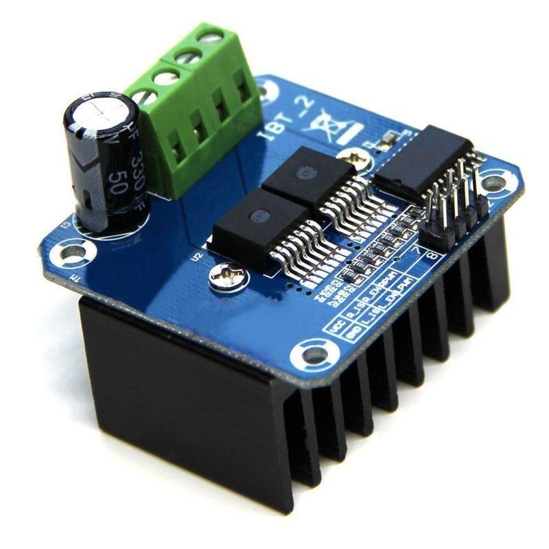
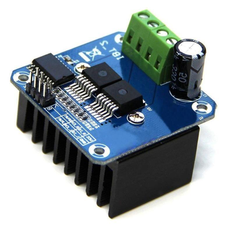
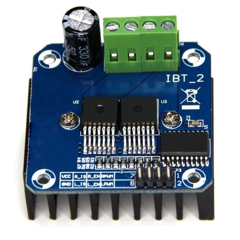
This driver uses Infineon chips BTS7960 composed of high-power drive full H-bridge driver module with thermal over-current protection. Double BTS7960 H-bridge driver circuit, with a strong drive and braking, effectively isolating the microcontroller and motor driver! High-current 43A.
Description
Operating Voltage 5.5 to 27V (B+)
Path resistance of typ. 16 mOhm at 25°C
Low quiescent current of typ. 7 uA at 25°C
PWM capability of up to 25 kHz combined with active freewheeling
Switched mode current limitation for reduced power dissipation in overcurrent
Current limitation level of 43 A typ.
Status flag diagnosis with current sense capability
Overtemperature shut down with latch behaviour
Overvoltage lock out
Undervoltage shut down
Driver circuit with logic level inputs
Adjustable slew rates for optimized EMI
74AHC244 Schmitt-trigger Octal buffer/ line driver for ESD protection (Inputs accepts voltages higher than VCC)
Getting started with the Double BTS7960B DC 43A Stepper Motor Driver H-Bridge PWM For Arduino
In this post I describe a slightly more complete solution that uses an Arduino controller with connected potentiometer to drive a motor via the Double BTS7960B DC 43A Stepper Motor Driver module from full reverse speed to full forward speed.
Hardware required
Connecting the Hardware
The following Fritzing diagram illustrates the wiring. B+ and B- at the top of the diagram represent the power supply for the motor. A 5k or 10k potentiometer is used to control the speed.

CODE
Here is the associated Arduino sketch:
/*
IBT-2 Motor Control Board driven by Arduino.
Speed and direction controlled by a potentiometer attached to analog input 0.
One side pin of the potentiometer (either one) to ground; the other side pin to +5V
Connection to the IBT-2 board:
IBT-2 pin 1 (RPWM) to Arduino pin 5(PWM)
IBT-2 pin 2 (LPWM) to Arduino pin 6(PWM)
IBT-2 pins 3 (R_EN), 4 (L_EN), 7 (VCC) to Arduino 5V pin
IBT-2 pin 8 (GND) to Arduino GND
IBT-2 pins 5 (R_IS) and 6 (L_IS) not connected
*/
int SENSOR_PIN = 0; // center pin of the potentiometer
int RPWM_Output = 5; // Arduino PWM output pin 5; connect to IBT-2 pin 1 (RPWM)
int LPWM_Output = 6; // Arduino PWM output pin 6; connect to IBT-2 pin 2 (LPWM)
void setup()
{
pinMode(RPWM_Output, OUTPUT);
pinMode(LPWM_Output, OUTPUT);
}
void loop()
{
int sensorValue = analogRead(SENSOR_PIN);
// sensor value is in the range 0 to 1023
// the lower half of it we use for reverse rotation; the upper half for forward rotation
if (sensorValue < 512)
{
// reverse rotation
int reversePWM = -(sensorValue – 511) / 2;
analogWrite(LPWM_Output, 0);
analogWrite(RPWM_Output, reversePWM);
}
else
{
// forward rotation
int forwardPWM = (sensorValue – 512) / 2;
analogWrite(LPWM_Output, forwardPWM);
analogWrite(RPWM_Output, 0);
}
}

