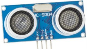
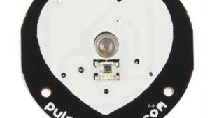
Description
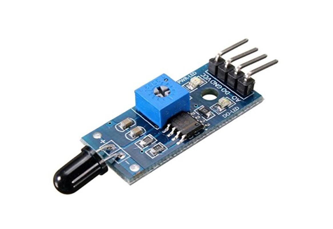
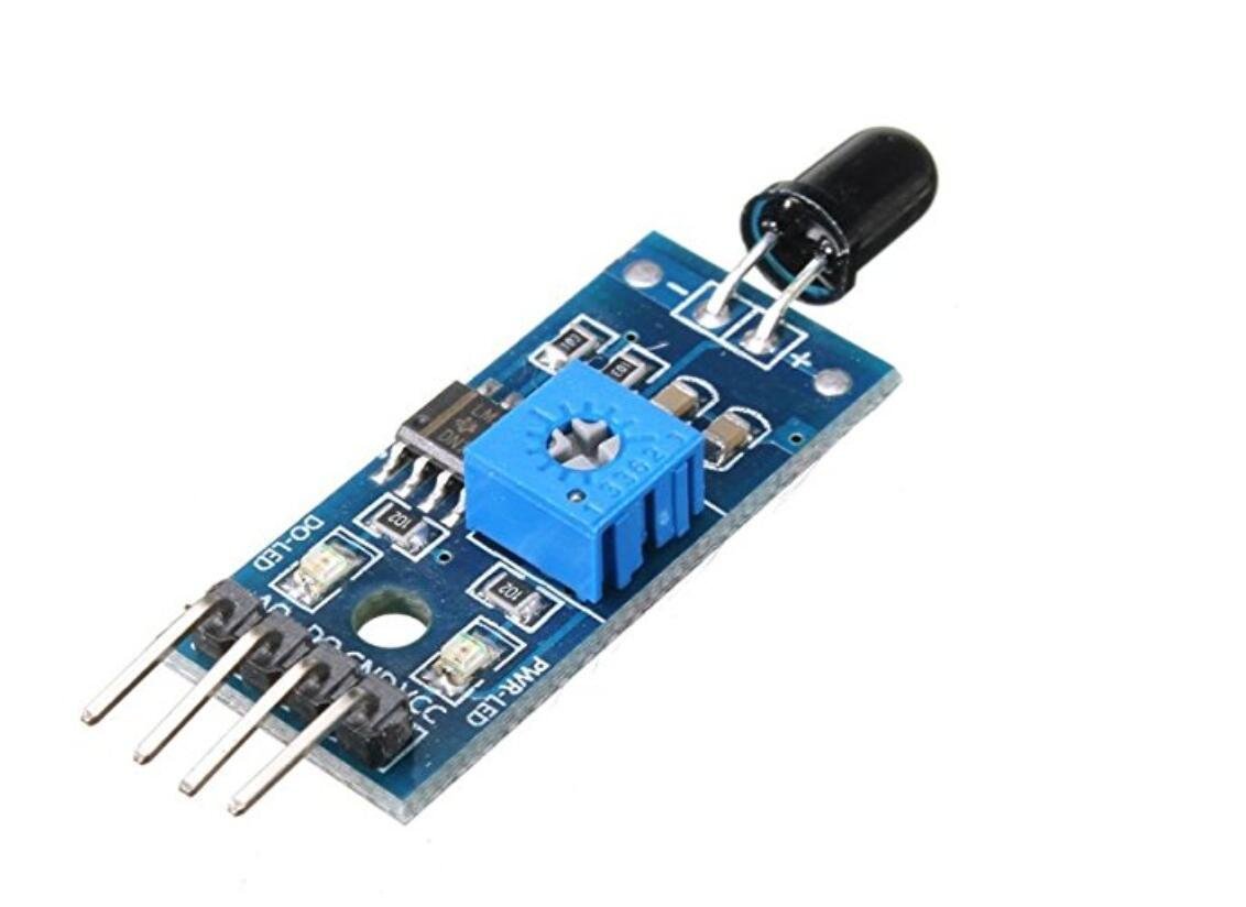
This module is sensitive to the flame and radiation. It also can detect ordinary light source in the range of of a wavelength 760nm-1100 nm. lighter flame test distance of 80cm, for the greater the flame, the farther the distance test.
Features:
- Detection angle is about 60 degrees
- Sensitivity is adjustable ( blue digital potentiometer adjustment in the module)
- Working voltage: 3.3V-5V
- Output form: DO digital Output and AO analog output
Getting Started with Flame digital sensor Module
Build fire alarm or fire detector using Flame sensor and Arduino board, the sensor basically detects IR (Infra Red) light wavelength between 760 nm – 1100 nm (nano meter) that is emitted from fire flame. Most of the flame sensors came with YG1006 sensor which is a high speed and high sensitive NPN silicon photo transistor.
Step1: Hardware required
Step2: Connecting the Analog output
Connect the flame sensor on the arduino UNO as shown below where Ao of the sensor is connected to the Analog pin 0 of the arduino, Vcc connected to the 5v, and gnd connect it to the arduino gnd pin.

Step3: Testing the circuit
After connecting the circuit, download a sample sketch here. after downloading extract it and open it. upload it to the arduino, after uploading open your serial monitor, according to the surrounding environment the sensor will indicates which state we are in. As shown below

Because of the darkness the serial monitor prints “Night” try to go on the sun you will get the message”day” which indicates that we are on the sunshine

Take your flame source like a candle or other source of flame put it in front of the flame sensor as shown below and see the message in serial monitor

In the serial monitor there will be a message which indicates that “THERE IS FIRE!!”, as shown below

Step4: Connecting the digital output
Connect the flame sensor on the arduino UNO as shown below where Do of the sensor is connected to the digital pin 2 of the arduino, Vcc connected to the 5v, and gnd connect it to the arduino gnd pin.

Step4: Testing the circuit
The only difference between the analog and digital is that the analog signal is change with time and the digital signal doesn’t varies, which means that we are going to get two state those are “THERE IS FIRE” or “NO FIRE”. You can download the sample sketch here upload the sketch
When there is no flame there is a message in serial monitor which says ” NO FIRE”. Which means no flame around, as shown below

But take the flame source in front of the sensor or take the sensor on the sun light there is a message in serial monitor says “THERE IS FIRE”, which means there is flame around, as shown below

Step5: Documents
Analog pin sketch, download it here.
Digital pin sketch, download it here.

