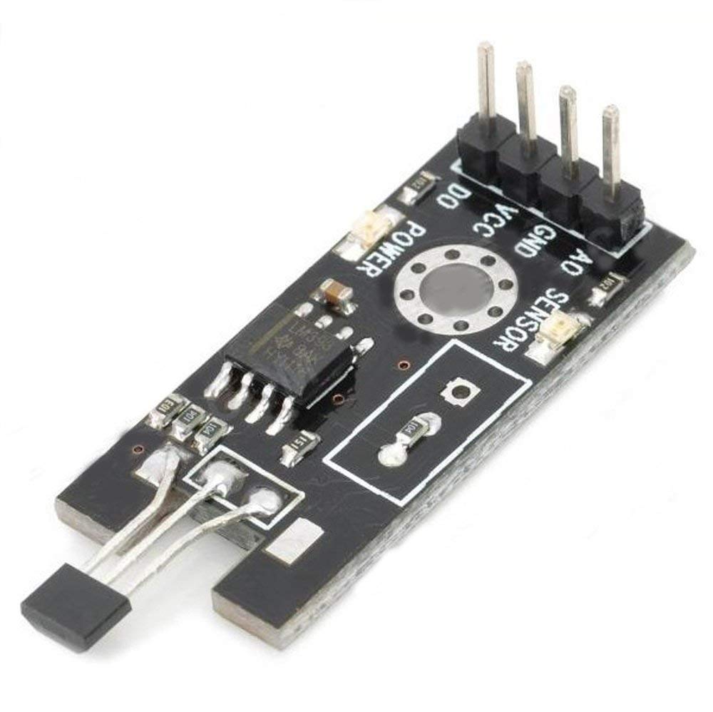
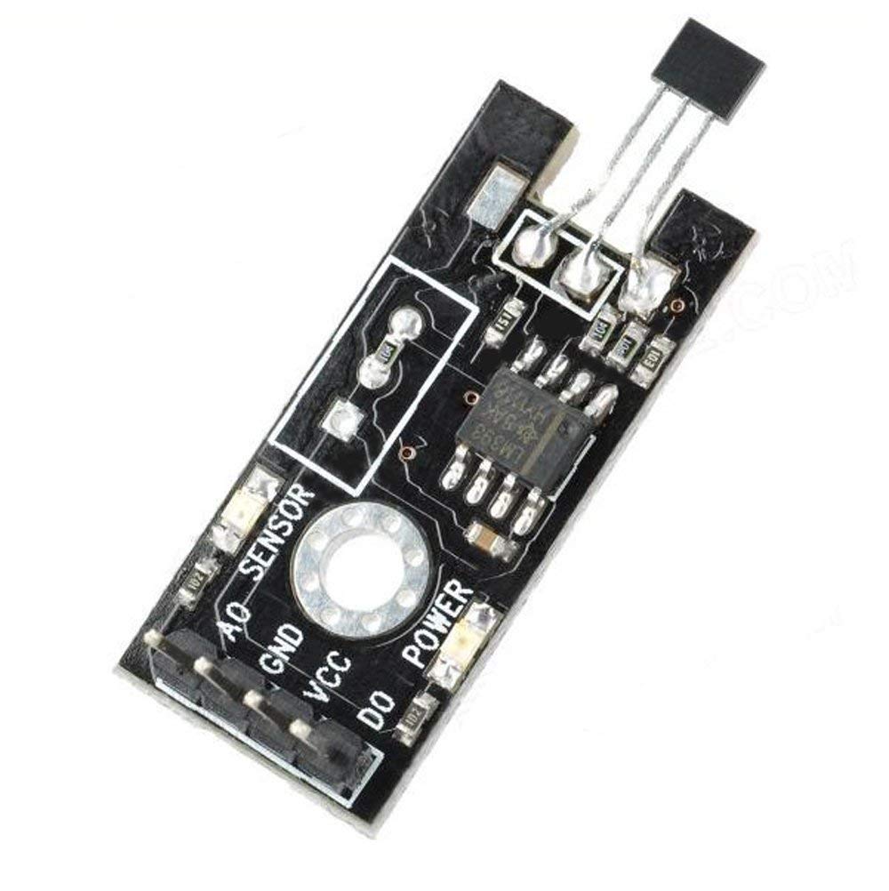
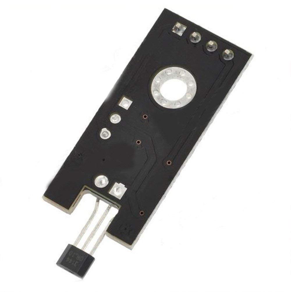
Description
A hall sensor Magnetic is a sensor that varies its output based on the presence or absence of a magnetic field. This means that the output signal produced by a Hall effect sensor is a function of magnetic field density around it. When the magnetic flux density around it exceeds a certain pre-set threshold value, the sensor detects it and generates an output voltage sometimes called the hall voltage to indicate the presence of the magnetic field.
they are used in many different applications. One of the popular applications of hall sensors Magnetic is in automotive systems where they are used to detect position, measure distance and speed. They are also used in modern devices like smartphones and computers and also used in different type of switches where the presence of a magnetic field is used to either activate or deactivate a circuit.
Features
- Hall sensor module using M44 switch
- With comparator regulating Hall signal AO,
- Real-time Hall signal output DO,
- steadier Hall signal output Comparator
- Output Current: 16mA
- Power Supply: 0-15 V DC
Getting started with Hall Sensor Magnetic Module Field Detecting Sensor For Arduino
For today’s tutorial, we will demonstrate how the hall effect sensor works by connecting it alongside a LED to an Arduino. The Arduino will be programmed such that when a magnet is brought close to the hall effect sensor, the LED comes on and when the magnet is removed, it goes off.
Parts required
Connecting the Hardware
The schematic for this project is a simple one, as all we have to do is connect the three pins of the hall sensor and an LED to the Arduino. Connect the components as shown in the schematics below.

With the schematics done, we can proceed to the code for this project.
CODE
int hallSensorPin = 2;
int ledPin = 13;
int state = 0;
void setup() {
pinMode(ledPin, OUTPUT);
pinMode(hallSensorPin, INPUT);
}
void loop(){
state = digitalRead(hallSensorPin);
if (state == LOW) {
digitalWrite(ledPin, HIGH);
}
else {
digitalWrite(ledPin, LOW);
}
}
Copy the code and Upload to Your Arduino board. You should see the LED switch when a Magnet is brought close to it.

